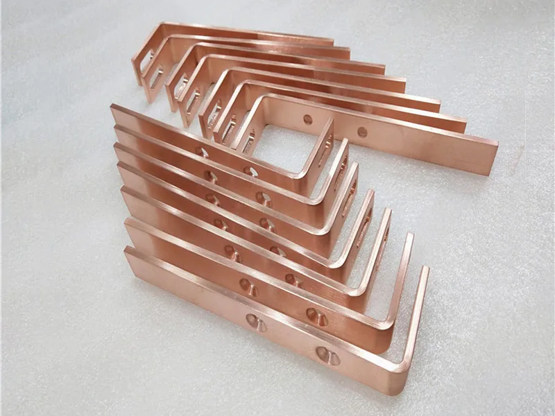
The Effect of the Width-to-Thickness Ratio on Busbar Bending
In power and electrical systems, the busbar aspect ratio refers to the ratio of the width to the thickness of a rectangular-section busbar (whether copper or aluminum). Within the busbar bending process, this aspect ratio determines the quality of the bend, the bending precision, and the specific parameters for die selection. Based on relevant industry standards and practical experience in busbar bending, the primary impact of the aspect ratio on the bending process is manifested in three key areas: minimum bending radius, springback control, and the specific busbar bending process techniques employed.
The width-to-thickness ratio of a busbar is a critical parameter in determining its bending process.
The greater the busbar aspect ratio (width/thickness), the more stringent the requirements become regarding processing techniques and equipment during bending; this primarily impacts the minimum bending radius and the stability of the busbar after bending. Specifically, this manifests as follows:
- High Width-to-Thickness Ratio (Wide and Thin): During edge bending (bending along the narrow side), the workpiece is prone to instability, wrinkling, or cracking, thereby requiring a larger bending radius.
- Low Aspect Ratio (Narrow and Thick): During flat bending (bending along the wide face), a greater bending force is required, but the material is relatively less prone to wrinkling.
Analysis of the Specific Impact of the Width-to-Thickness Ratio on the Busbar Bending Process
3. Core advantages (compared to traditional manual or hydraulic processing)
The minimum bending radius of a busbar is directly related to its thickness and width, while the width-to-thickness ratio determines the specific bending method to be employed, as well as the corresponding radius standards.
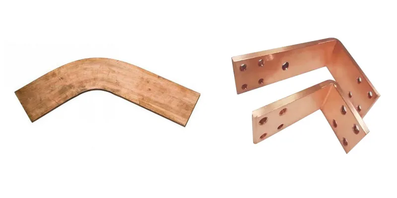
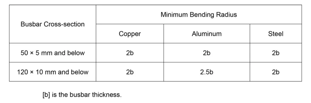
- Flat Bending (bending along the width direction): In the busbar bending process, the minimum bending radius is primarily dependent on the busbar thickness. For instance, industry standards in the electrical sector specify that for rectangular copper or aluminum busbars undergoing flat bending, the minimum bending radius is equal to twice the thickness.
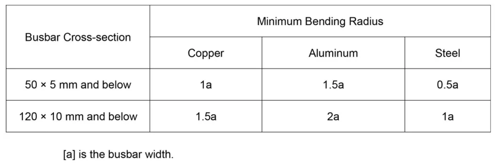
- Edge Bending (bending along the thickness direction): The minimum bending radius is primarily dependent on the width. For instance, industry standards in the electrical sector specify that for rectangular copper or aluminum busbars undergoing edgewise bending, the minimum bending radius should be 1 to 2 times the width. When the busbar width is substantial (i.e., the width-to-thickness ratio is high), a 90° edgewise bend is generally not recommended, as the required bending radius would be excessively large, making the fabrication process difficult.
3. Impacts on Busbar Bending Quality and Defects
The width-to-thickness ratio directly influences the material flow and stress distribution of the busbar during bending; an improper ratio or manufacturing process can lead to defects:
- Excessive Width-to-Thickness Ratio (Busbar is too wide and thin): During vertical bending, the outer side of the busbar (tension side) is prone to cracking due to excessive stretching, while the inner side (compression side) is prone to wrinkling and bulging caused by material accumulation.
- Bending Springback: The width-to-thickness ratio also influences the magnitude of springback; non-uniform thickness or mechanical properties in copper busbars can lead to inconsistent springback, thereby compromising the precision of the bending operation. Given a constant bending radius and identical busbar material, busbars with a high width-to-thickness ratio—as their width increases—exhibit a more uniform distribution of plastic deformation across the material cross-section. Consequently, lateral deformation is constrained, the proportion of elastic recovery remains relatively consistent, and the springback angle demonstrates greater uniformity, making linear compensation on CNC busbar bending machines easier to implement. Conversely, busbars with a low width-to-thickness ratio exhibit significant shifting of the neutral axis; the disparity in elastic recovery between the inner and outer radial surfaces widens, rendering the springback angle difficult to predict and increasing the susceptibility to torsional deformation.
In response to this impact, Robin—a technician at the busbar manufacturer SUNSHINE—conducted two experiments in the busbar bending machine workshop:
Using the same busbar bending machine, both were bent at 90°.
Case 1:
For a 100×10 mm copper busbar with a width-to-thickness ratio of 10, setting the compensation angle to 3° during bending resulted in an angular error essentially controlled within ±0.3° after continuously bending 10 pieces.
Case 2:
For a 30×10 mm copper busbar with a width-to-thickness ratio of 3—assuming a compensation angle of 3°—the resulting bend angle may fluctuate between 86° and 88°, and a distinct “bulge” is evident on the side of the bend.
Conclusion:
A large width-to-thickness ratio facilitates precision control during mass production, whereas a small width-to-thickness ratio requires the operator to frequently fine-tune the pressure based on the hardness of each batch of material.
Requirements for Processing Techniques and Equipment
Core Impact on Process Requirements:
Variations in the width-to-thickness ratio result in a fundamental alteration of the internal stress distribution pattern within busbar materials when subjected to mechanical loads.
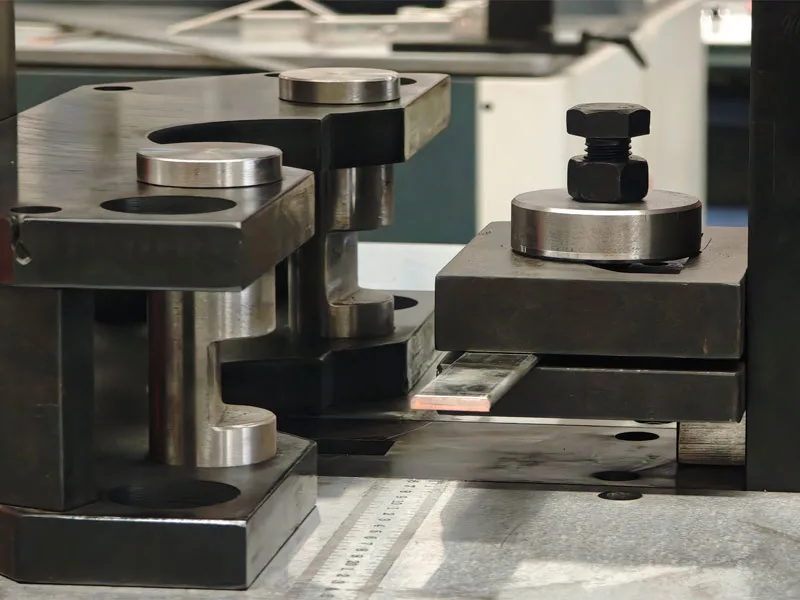
- Instability and Wrinkling in Edge Bending: During the edge bending process for busbars—particularly those with a high width-to-thickness ratio (i.e., wide and thin)—the compressive stresses exerted on the inner edge during bending can easily trigger structural instability. Consequently, the busbar may wrinkle out-of-plane, much like a sheet of folded paper. To prevent such defects, the manufacturing process mandates the use of specialized dies equipped with powerful auxiliary clamping mechanisms. Furthermore, “guide plates” must be employed during the bending operation to restrict displacement in the thickness direction. Modern High-Precision Busbar Processing Machines: The MAC CNC Busbar Bending Machine utilizes servo control technology to better accommodate the processing requirements of busbars with varying width-to-thickness ratios, thereby minimizing errors.
- Cross-sectional Distortion in Flat Bends: For busbars with a low width-to-thickness ratio—whose cross-sectional profile resembles that of a “square bar”—bending causes the copper material to flow laterally. This lateral flow results in a pronounced “bulging” effect on the side faces of the busbar at the bend location. Consequently, when processing flat bends, it is essential to allow for a larger length compensation margin when calculating the positions for punched holes, as the lateral displacement of the material alters the actual location of the neutral axis.
Requirements for the Performance of Processing Equipment
A CNC busbar bending machine must be capable of accommodating the physical challenges posed by busbars with varying width-to-thickness ratios.
For copper busbars with a low width-to-thickness ratio (i.e., those of substantial thickness)—particularly those exceeding 15 mm—the equipment demands extremely high static rigidity. Should the rigidity of the machine head prove insufficient, even minute frame deformation can result in the failure of springback compensation. Conversely, for copper busbars with a high width-to-thickness ratio (i.e., thin bars), the critical factor lies in the precision and finesse of pressure control; the equipment must be outfitted with a servo-driven busbar bending system to prevent cracking or over-bending caused by pressure overshoot at the precise moment bending commences.
In summary
| Impact Dimensions | High aspect ratio (wide and thin) | Low Aspect Ratio (Narrow and Thick) |
|---|---|---|
| Key Challenges | Prone to wrinkling and cracking during vertical bending; springback is difficult to control. | Flat bending requires higher-tonnage equipment; the bending radius is limited by material thickness. |
| Minimum Bending Radius | Large vertical bend radius (related to width; typically 1–2 times the width) | Large bending radius (dependent on thickness; typically 2 times the thickness) |
| Process Trends | Whenever possible, avoid 90-degree vertical bends; prioritize the use of horizontal bends or other connection methods. | Suitable for vertical bending; for horizontal bending, ensure that the mold's R-radius is sufficient. |
| Key Points for Quality Control | Check for cracks, creases, or bulges at the bends. | Check the fillets at the bends to ensure they are smooth and free of cracks. |